Promoting Excellence in HO Scale Vehicle Modeling
River Point Station Service/Utility Bucket Truck Acccessory Installation by Ronald Elsdoerfer
Special thanks to Ron Elsdoerfer of River Point Station for providing these tips for installation of the River Point Station service/utility body accessories!
![]()
Auxiliary Beacons:
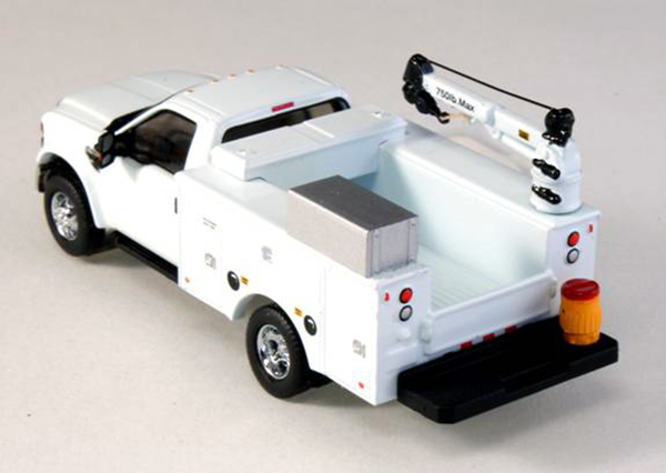
Two extra beacons are packed in a small bag and placed under the lower, inner blister of the model packaging. They are included in the event a modeler wants to add them on top of the sponsons. To drill holes for the beacons, look at the truck from underneath to see a series of cored hole in the undersides of utility box’s sponsons and the rear bumpers. These may be drilled through to locate various accessories — some of those accessories aren’t yet available.
The rearward most holes in the sponsons are for mounting the 2-optional beacons. Some real trucks have those beacons, others don’t. We have elected this method because it is easier for customers to drill a couple holes (0.75 mm or 1/32”) than to patch unwanted holes and have to match paint. Please note: The antiskid surface shown on top of the sponsons in the photo above will be on the fire truck versions of the body—the standard service body normally has a smooth surface.
Crane Truck:
A crane truck may also be easily built using the basic service truck (in color of choice) and adding the crane accessory set (SKU #537-5252.49).
By drilling the rear most hole (2 mm or #47) on the passenger side sponson, it provides the correct placement for the crane found in the optional accessory set. In most such cases, there is no beacon on the driver’s side, so that core should not be drilled through!
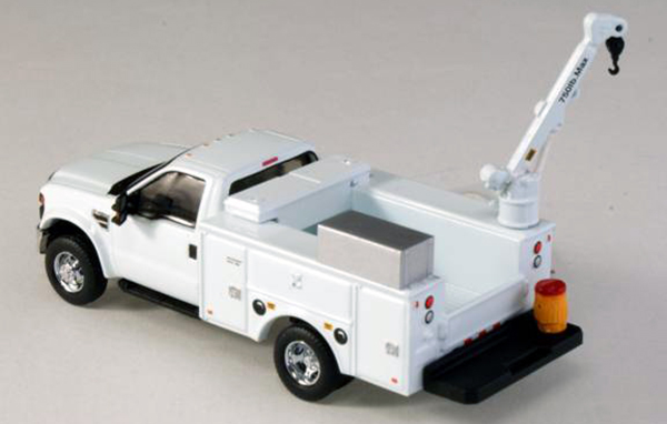
Standard boom mount — Use the crane straight from the package. Note: The hoist cable, shown in the photo above, is not furnished; it was made from a scrap of 0.008" wire. The crane in this photo has had some of its details picked-out with black paint. Those hydraulic motors could be filed off and replaced with styrene rod for greater depth. The crossover toolbox was modified from one in RPS’ toolbox set, and the water jug comes with the crane; the large silver tool locker is part of a future detail set. The hook is a separate piece, so it can be mounted plumb, or angled for stowing, as shown above. A piece of dental floss serves a sling.
Elevated boom mount—The cranes are too small to make them articulated. However, using a jewelers’ saw, one can carefully trim the boom from the trunnion, and reposition it with ABS compatible glue. Below is a crane shown in an elevated position. The conversion took about 10-minutes. Of course, extra detailing (as above) may be easily added. The water cooler is unrealistically positioned on the bumper for clarity.
The crane sets are also furnished with a riser (not shown). The riser raises the crane when mounting the crane on a flatbed.
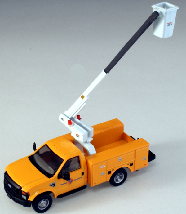
Extending the Bucket Boom
In order to keep the bucket boom accessories within scale dimensions, it was not physically possible to make a working, telescoping boom. Obviously, for added realism and variety it would be nice to extend its reach, as shown below, for use in dioramas and other scenes. The procedure is quite simple!
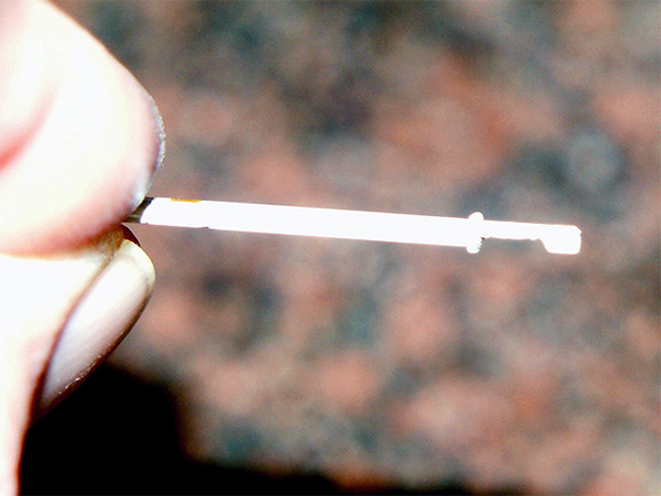
Begin by filing the “extendable” telescopic portion of the boom, between the knuckle and the end of the outer boom to half its thickness—about 0.75 mm (0.03”)—using the mold parting lines at the top and bottom of the boom as a guide.
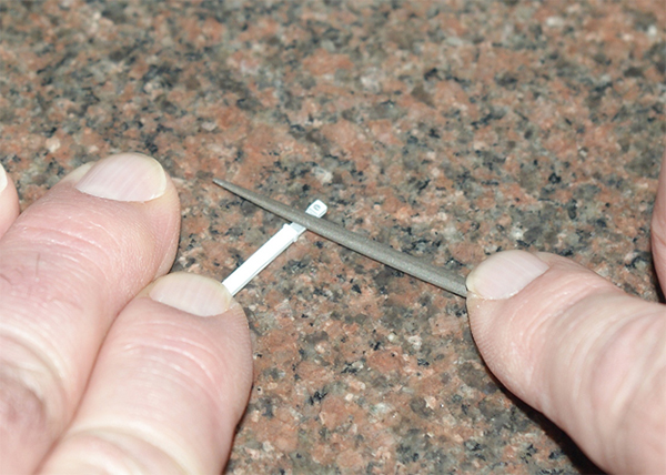
Work carefully. A small needle file works best, but one could also scrape the area down to the needed thickness. Check periodically to ensure that the resulting land is flat and parallel to the reverse side of the boom. Note: Placing the boom on a piece of cardboard will make the work easier, since the boom is less likely to slide around. The cardboard will also support the cantilevered end of the boom against the filing forces, and protect the flange around the end of the outer boom. The finished part should look like this:
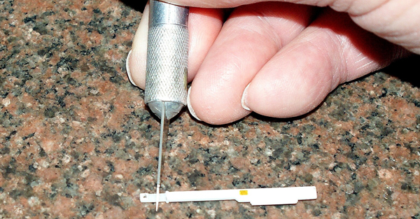
Once satisfied with the modification, dissect the boom halfway between the knuckle and the flange, as shown by the red line, in the photo above. It is best to do this with a sharp hobby knife, while resting the boom on the cardboard, as was done while filing the part.
Now make the extension. Cut a piece of Evergreen #154 styrene 1.5 x 2.0 mm (0.06” x 0.08”) a little longer than the desired extension’s length. Remember, this is a medium duty truck and lift with single telescoping extension; so the extension cannot be longer than 35 mm (1-3/8”). This time, file both ends to about half the thickness. Ensure that the lands are flat and parallel, and that the notched ends are square. (By leaving the extension a little longer than desired, it is easier to file the ends flat and parallel.)
When satisfied, simply trim the ends to length, matching the ends of the previously cut boom parts. This will ensure a strong lap joint. Cement the 3-parts together with ABS compatible cement. Liquid cement welds the parts to form a stronger interface. Once the cement has dried, clean the joints with a file and paint the boom in the color of choice
Finalize assembly and display. Once everything is positioned as desired, cement the remaining joints to minimize stress on the locating pins. Remember, the pins are only for locating—they are not intended as working bearings.
River Point Station Div.
International Technologies, Inc.
115 Maple Street
Warwick, RI 02888-2130